Wind Your Own RF Matching/Isolation Transformer
The simple DIY project for a broadband loop antenna
© 2013 Bruce A. Conti
It's the question I'm asked most often about broadband loop antennas such as the Delta, Flag, and SuperLoop; "Where can I find the matching transformer?" Unfortunately the type of transformer required for this antenna is typically not available as a mass-produced complete assembly from commercial retailers. Because the broadband loop antenna is floating (no connection to ground), the antenna connections must be isolated from the lead-in. If the high impedance winding of the antenna is physically connected to the low impedance winding of the lead-in, then the loop antenna will no longer be floating which defeats the noise-reduced design of the inherently low-noise loop configuration. Those commercially available matching transformers, often referred to as 'baluns', usually have an internal common ground connection between the high and low impedance windings. The common ground might be perfectly fine for dipole and vertical whip applications, but not for a loop. Therefore to guarantee isolation requires either hiring someone to build a custom transformer, or the more economical option - DIY - do it yourself.
DIY Option #1: The Mini-Circuits Shortcut
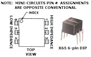
There are two options for DIY. Option number one: Order an RF transformer from Mini-Circuits (or an eBay seller), then complete the assembly by installing the Mini-Circuits trasformer in a plastic chassis with appropriate antenna and lead-in connectors. This is the easiest of the two DIY projects. However the Mini-Circuits transformers are so tiny that they can be blown up by static electricity or a nearby lightning strike. Although I've had relatively good experience with Mini-Circuits transformers, even I've lost a few over the years. However, if the antenna is in a location where the risk of lightning is low, then you could probably get away with the Mini-Circuits DIY shortcut. The Mini-Circuits transformer comes in a 6-pin DIP (X65 package) like an integrated circuit. If the transformer is mounted on a DIP socket, then at least it can be easily replaced if damaged. When placing a Mini-Circuits order, it's a good idea to buy a couple extras just in case.
Note that the Mini-Circuits "X65" pin number assignments are opposite convention for a dual in-line package. Normally the top left at the index mark would be assigned pin 1, but Mini-Circuits designates it as pin 6. Pins 4 and 6 are the low impedance, 1 and 3 the high impedance connections per the Mini-Circuits pin number assignments.
Parts List
(1) Mini-Circuits 16:1 transformer part number T16-6T X65 www.minicircuits.com
(1) 6-pin DIP socket
(1) bulkhead/chassis mount coax connector; BNC or SO-239
(2) binding posts
(1) small weather-proof plastic chassis
(x) hook-up wire
DIY Option #2: Wind Your Own
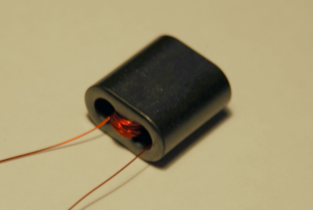
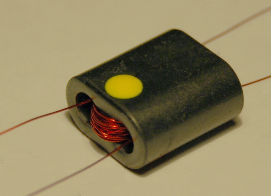
Option number two: Winding your own RF matching/isolation transformers for broadband loop antennas is super easy, especially if a binocular ferrite core is used. Wire is threaded through one hole and then back through the other hole of the binocular core to complete one turn of a transformer winding. The number of turns is determined by the square root of the impedance ratio. For a 16-to-1 (16:1) impedance ratio, the actual transformer winding ratio is 4:1. (The square root of 16 is 4.) In other words, for for every four high impedance turns/windings, you'll need one low impedance turn/winding. 20 turns for the high impedance and 5 turns for the low impedance works well and maintains the desired 4:1 ratio. First wind 20 turns for the high impedance on the ferrite core (photo below - left), then 5 turns for the low impedance. Mark the high imedance end (photo below - right) so you don't forget which is which during final assembly.
Parts List
(1) Fair-Rite binocular type-73 ferrite core, model 2873000202 (in Newark Electronics online catalog)
(x) light guage (30 AWG typ.) solid hook-up wire or enamel-coated magnet wire
(1) bulkhead/chassis mount coax connector; BNC or SO-239
(2) binding posts
(1) small weather-proof plastic chassis
Final Assembly
To complete either the Mini-Circuits or 'wind your own' assembly, the transformer is mounted inside a plastic chassis with the appropriate connectors. Two binding posts are used to connect the high impedance windings to the antenna. A BNC or SO-239 chassis-mount coax connector is used to connect the low impedance to the lead-in and receiver. A dab of silicone RTV can be applied to secure the transformer, and to seal the chassis for additional protection against rough handling and extreme weather conditions.
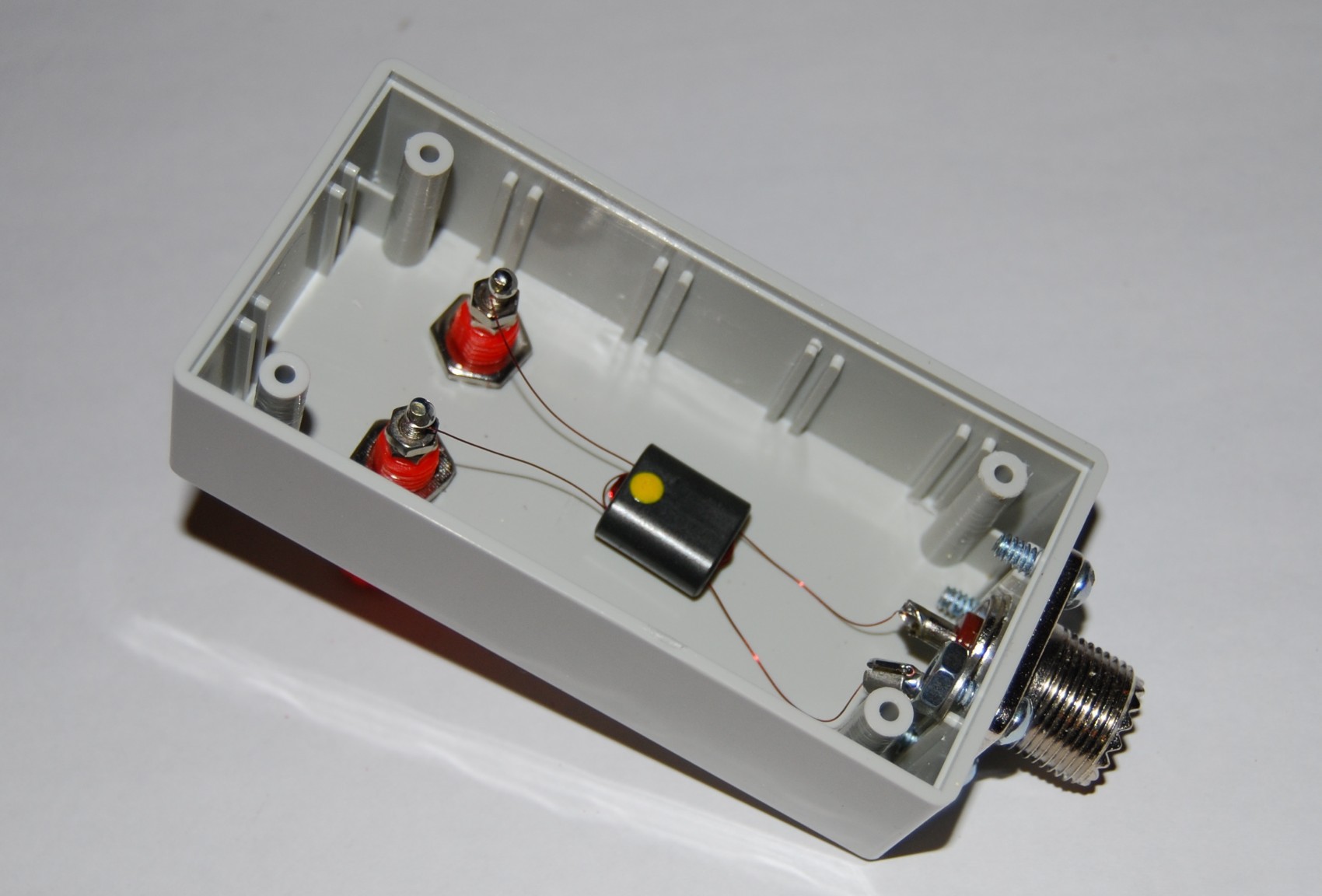
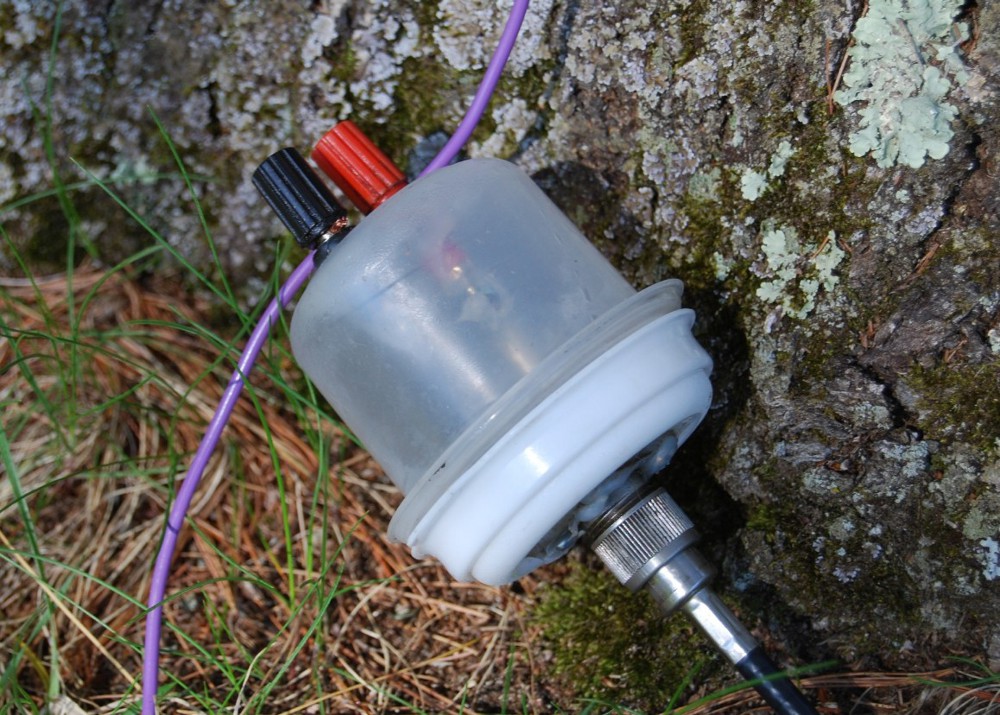
The completed assembly in a plastic chassis with binding posts and coax connector (left), and a completed assembly using a food storage container for a chassis (right).
Upon completion of the assembly, it's always a good idea to check connections with an ohmmeter prior to installing in the field. The binding posts should "ohm out" as zero ohms or a short-circuit between them. Between the shield and center of the coax connector should also measure zero ohms. Measurements between the coax connector and binding posts should be open circuit.
While the instructions here are specifically for a 16:1 transformer, the same methods can be applied to any desired impedance ratio. Use the square root rule for winding your own, or look for the comparable model in the Mini-Circuits catalog.
73 and Good DX!
Return to ¡BAMLog! home.