Comparison of Delta Variants
Delta, Double Delta, and Cross-Phased Delta Variable Termination Loop AntennasRev 1.10, 2/17/13: Added EZNEC model results to show 90° range of motion for Cross-Phased Deltas.
Rev 1.20, 2/18/13: Added imbedded links for SuperLoop, Termination Gizmo, and phasing units.
© Bruce A. Conti WPC1CAT
This is a cursory comparison of three different configurations of the variable termination Delta broadband loop antenna as implemented in medium wave AM broadcast DX applications. The three configurations are: A basic terminated Delta measuring 100-ft horizontal by 30-ft tall as used in various DXpeditions, the 110-ft horizontal by 18-ft tall Double Delta implemented in the 2013 CMMC DXpedition, and the 100-ft by 30-ft Cross-Phased Deltas of the 2012 Prince Edward Island DXpedition. All three configurations are modeled with EZNEC and compared albeit subjectively from experience.
Basic Delta Configuration
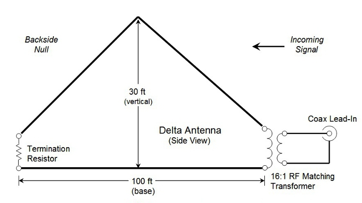
The Delta is part of the family of terminated broadband loop antennas that includes the Flag, Pennant, and SuperLoop. The Delta and SuperLoop configurations are noted for low angle performance at medium wave frequencies.
2013 CMMC Double Delta
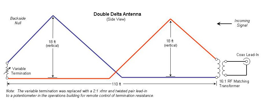
The Double Delta is a "split" or "twisted" loop configuration leveraged off of the Double Half Delta Loop (DHDL) design of the TX3A Chesterfield Islands DXpedition. It's worth noting that the CMMC antenna layout was not 'to spec' per the "D-Kaz" antenna dimensions of the Neil Kazaross design. Instead for expediency the antenna was erected as dictated by supports already in place (a tree and a pole) at the CMMC site. Still, Kazaross confirmed that the dimensions of this CMMC antenna were reasonable.
2012 Prince Edward Island Cross-Phased Deltas
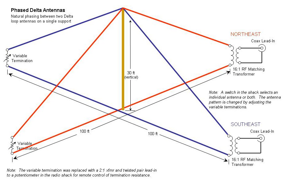
The Cross-Phased Delta configuration has been implemented successfully during two DXpeditions on Prince Edward Island, most recently November 2012 with two Deltas measuring 100-ft horizontal base x 30-ft tall apex supported by a single mast. In 2010 a 60 x 23-ft version was used. The antennas were aimed northeast and southeast. The Cross-Phased Deltas depend primarily upon a 'natural' phase relationship between the two antennas. An antenna switch allows for selection of an individual Delta antenna or connection to both. When both antennas are switched on, the variable terminations of each antenna are adjusted to steer the direction of the null. Terminations can also be adjusted to steer a figure-8 beam, produce side nulls, or maximize gain for a particular target. Change physical antenna positions, or add 180° antenna load/source switching and the possibilities seem infinite.
The Comparisons
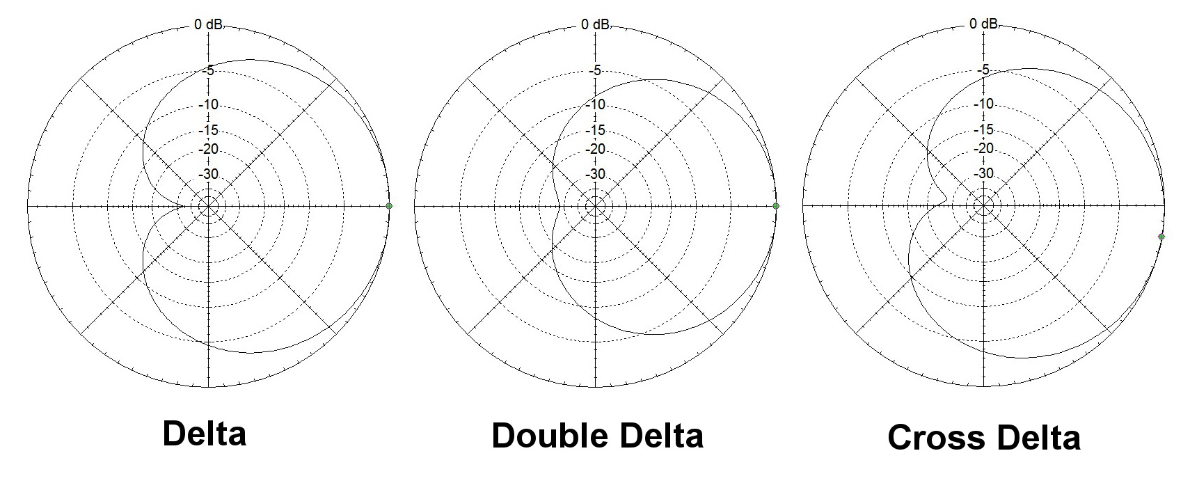
Experiences with these antennas are comparable to results obtained through EZNEC models. The EZNEC results shown here are 30° azimuth patterns at 1000 kHz for demonstration purposes.
Cross-Phased Range of Motion
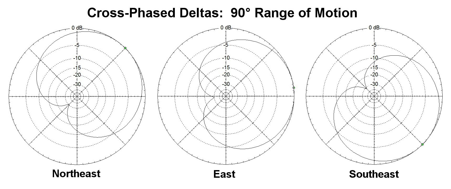
EZNEC models demonstrate the 90° range of motion within a quadrant for the Cross-Phased configuration of northeast and southeast Deltas. Using an antenna switch to select only the northeast Delta results in a northeast cardioid with a deep southwest null when the termination resistance is adjusted to the nominal value, 1100 ohms typical. Similarly the southeast Delta is selected with the termination at nominal for a southeast beam with a northwest null. When both antennas are selected, termination resistances are adjusted to steer the beam within the northeast to southeast quadrant, usually by reducing the termination resistance of one Delta while slightly increasing resistance of the other. In the above EZNEC model results, the northeast Delta termination resistance is 400 ohms, and the southeast Delta 1420 ohms, to produce an easterly beam with a westerly backside null.
This 'natural' phasing approach is simple to implement. No complicated circuitry; just wire, transformers, a switch, and potentiometers. The addition of a Connelly WA1ION "Termination Gizmo" direction reversal circuit would allow for beam steering within any quadrant. A phasing unit such as the Quantum Phaser or a WA1ION homebrew model can be used to obtain additional null depth when needed. Natural cross-phasing that takes advantage of the interaction between co-located antennas can be applied to any of the terminated broadband loop antennas. At the WPC1CAT antenna site, similar results have been obtained using cross-phased northeast and south variable termination SuperLoop antennas sharing a mast.
73 and Good DX!
Return to ¡BAMLog! home.