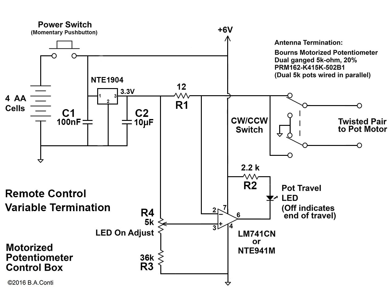
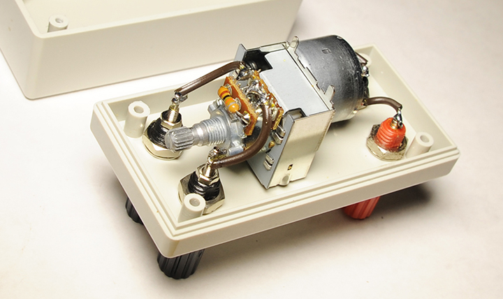
A motorized potentiometer is used as a variable termination for broadband loop antennas, including the Flag, Pennant, Delta, and SuperLoop. It replaces transformer-coupled and vactrol terminations. The transformer-coupled termination has been determined to cause at least a minor effect on the backside null. Coupling to the antenna is eliminated by the isolation of the potentiometer from the remote control line. Vactrol termination requires power applied at all times to maintain its setting. With a motorized potentiometer termination, power is only applied to the motor when pressing the momentary pushbutton switch to adjust the potentiometer. Once a desired value is 'tuned in', power is turned off when the pushbutton is released. Set it and forget it.
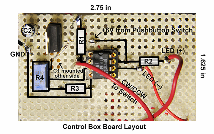
If the LED turns on when the pushbutton is pressed, then the potentiometer motor is in motion and the resistance is changing as the motor rotates the potentiometer shaft. When the remote potentiometer end of travel is reached, the current increases due to the increased load on the motor. The op amp circuit measures the voltage drop across the 12-ohm resistor (R1). If the voltage drop across the resistor increases due to increased current, then the LED is turned off which indicates end of travel. The 5k trim pot (R4) sets the LED on/off voltage. This allows for variation between potentiometer motors and differences in voltage drop across various control cable (twisted pair) lengths. Use the CW/CCW (clockwise/counter clockwise) toggle switch to reverse direction of travel. The 3.3V regulator maintains a consistent control voltage as battery voltage varies with use.
|